Floating Cap
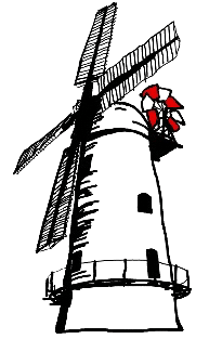
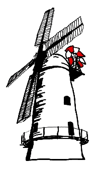
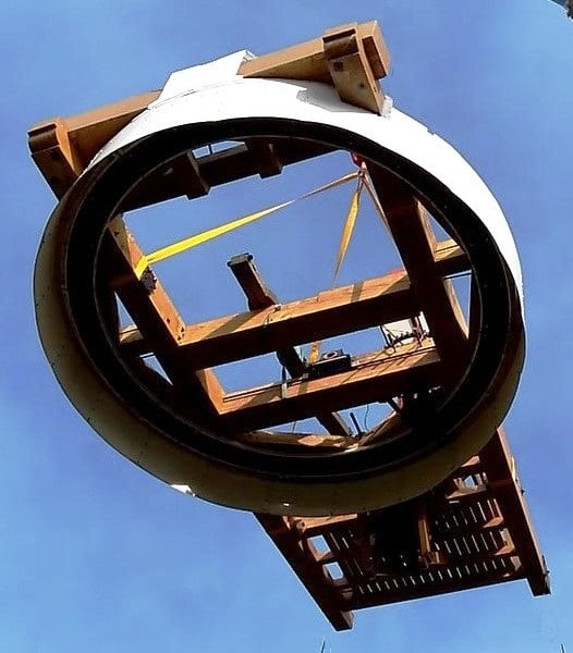
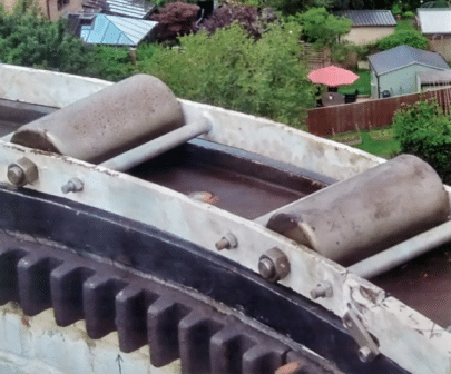
The cap and its contents are not attached to the brick tower. It floats on top of the building so it can rotate 360°, it rotates on roller bearings (like rolling pins).
The enormous sails, the machinery inside the cap and the red and white fantails are all supported by a wooden frame. In total they weigh about 12 tons, the weight of 8 family cars and are free to rotate.
Fantail
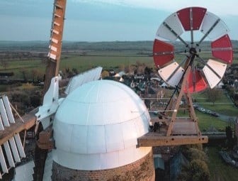
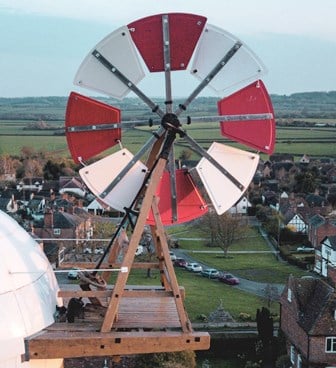
The fantail is perhaps the least appreciated part of the windmill, it moves the 12 ton cap through 360° to keep the sails facing the wind. Its red and white fan blades rotate clockwise or anticlockwise whenever the wind changes direction, to ensure the sails are facing directly into the wind. It drives a shaft which links into a mechanism inside the cap to move the cap and its contents.
Headframe
The headframe is a rectangular platform made from large dimension oak timbers. At one end it supports the weight of the sails and at the other the fantail and its frame. It has to be sturdy to carry the weight and to withstand the stresses created when the sails are turning.
Bearings
At the top of the brickwork are 24 cast iron tapered roller bearings (like rolling pins) that enable the cap to move freely around the top of the brick tower. These bearings support the weight of 12 tons and the stresses of the sails turning; remarkably they are the originals from 1832.
The Cross and Brakewheel
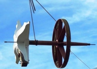
The sails are fixed to the large cross which protrudes from the cap. The cross is attached to the brakewheel which sits above the centre of the mill. As the wind moves the sails the brakewheel rotates providing power to all the moving parts of the windmill.
Brakewheel
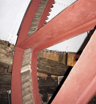
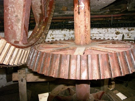
The 2.75 meter diameter wheel is made of cast iron with wooden teeth. They are made with wood that has a wavy grain such as apple, pear or oak beam; wood with a wavy grain does not split on impact.
Wallower
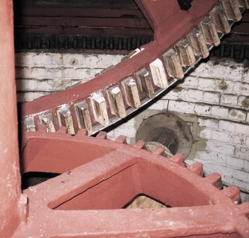
As the brakewheel rotates it meshes into another cogged wheel, the wallower, which powers the equipment on the various floors of the mill. It converts horizontal power from the sails into vertical power down the windmill.
Metal on Wood contact
Within the windmill, inter-connecting cogs will have metal on wood contact. The drive shaft has 120 teeth made out of wood which mesh with the metal teeth of the wallower. Metal-on-metal contact is avoided to reduce noise, avoid sparks (which can be very dangerous), prevent wear-and-tear and is easier to repair.
Note the wallower has an odd number of teeth whereas the other wheels have an even number. This insertion of a “hunting cog” ensures that the engaged wheels mesh differently at each revolution to prevent uneven wear.
Sails
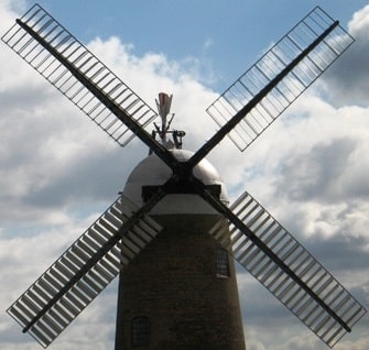
Each of the four sails weighs approximately one ton and has 42 moveable white panels called shutters. All 168 shutters on the mill are connected and can be moved through 90 degrees.
This produces maximum drive with 66 square metres of shutter facing the wind.
Spider
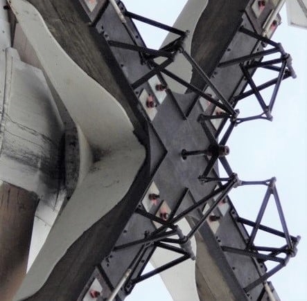
In the centre of the sails is a large black cross which is called the spider, this links all four sails to allow all of the shutters to open and close simultaneously.
Gallery
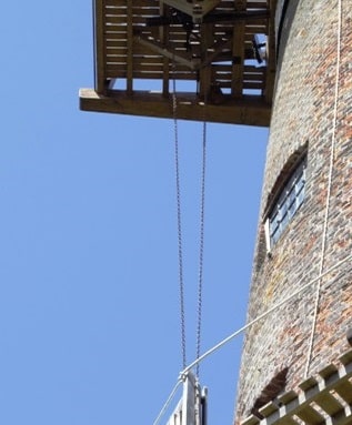
The gallery is the wooden platform on the outside of the mill at the spout floor level. On this floor are most of the controls and adjustments for the mill.
Striking Chain
On the gallery is the striking chain which is the chain mechanism used by the mill operator to open and close the shutters. The striking chain is directly connected to the spider via linkages in the cap.
The gallery is not for public viewing. In fact it is a very dangerous place to be.
Millstones
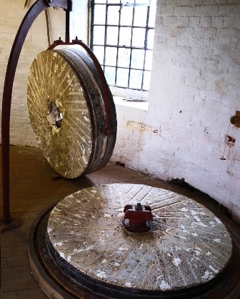
The grain is fed from bins on the floor above via a chute into the centre of the two flat millstones. The bottom one (bed stone) is fixed in place and the top one (runner stone) is driven around using the power from the floor below.
Both stones have a pattern of channels cut into them, so the uneven surface crushes the grain and also moves the ground flour to the outer edge of the millstones.
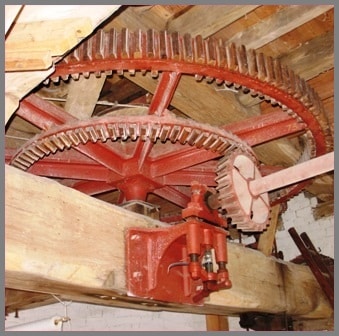
Great Spur Wheel
This is on the floor below directly under the millstones and is driven by the mechanism in the cap; it provides power to many working operations in this area.
Cranked Handle
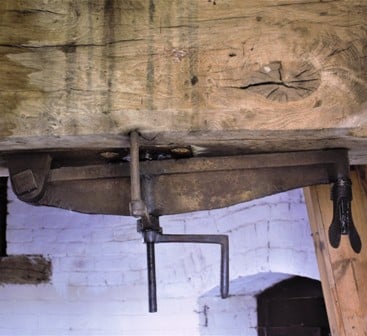
This is below the beam and is used to engage the drive for the runner stone when the sails are not turning. It connects the power to the runner stone which is positioned above it.
Tentering Gear
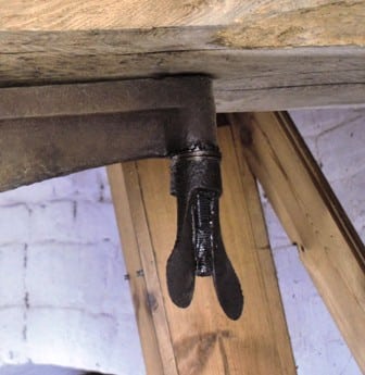
The butterfly handle lifts and lowers the heavy runner stone when milling is in progress, i.e. it controls the quality of the flour.
Governor
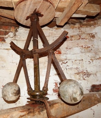
A set of spinning balls that use centrifugal force to act on levers to keep the gap between the grinding stones constant as the wind changes speed. This ensures uniform particle size and quality of flour.
Sack Hoist
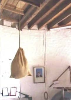
Local farmers would bring sacks of grain to be milled into flour. The sacks were pulled up to the top of the mill by the sack hoist. As the sacks rose up the mill they would push open the wooden flapper doors on the floor and as the sack cleared each door they would close again.
The flapped doors on the top of the sack hoist are deliberately high to make it easier for the miller to transfer the sacks to the nearby grain bins. The grains would be tipped out and they would slide down chutes to the floor below.
Sieving and bagging the flour
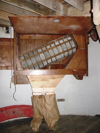
On the second floor the flour would be sieved and graded using a wire machine driven by belts from the floor above. This would first separate the valuable flour from the husks and other unwanted material and then separate the flour into three different grades to be bagged into sacks.
